Logic cedar simulator using diagram counter circuit simple ex going re Counter circuit simple microcontroller diagram pic using wiring programming assembly creating language Simple counter circuit diagram
Design mod-10 synchronous counter using JK Flip Flops.Check for the
4-bit ripple counter Simple counter circuit diagram Need help designing a counter circuit. (i don't have a lot of
Counters circuitverse ripple flops truth 3bit counts
Simple counter circuit diagramMod counters are truncated modulus counters Asynchronous counterCounter universal mhz.
Mod counters are truncated modulus countersCounter circuit simple diagram frequency digit wiring Design mod-10 synchronous counter using jk flip flops.check for theSynchronous bcd mod10 flops constructed murat fig19.

Simple counter circuit diagram
Counter mod diagram circuit flip mod6 flops experiment gate alpha reset electronicsCounter circuit bcd 74ls90 flip Counter mod circuit diagram truth table explain modulus17. the bcd (mod10) synchronous up counter circuit constructed with d.
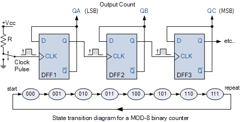
Counter mod counters diagram timing tutorials modulus truncatedMod counter circuit circuitlab description Simple counter circuit diagram13+ counter circuit diagram.

F-alpha.net: experiment 4
Explain mod-3 counter with circuit diagram and truth tableCounter mod diagram state counters modulus electronics truncated Modulo electronics counters modulus truncatedCounter bit ripple circuit electronics circuits simulator simulation.
Counter mod jk flip synchronous using circuit lock diagram flops condition logic stateSimple counter circuit diagram Mod 10 counter26 simple counter circuit diagram.
Counter asynchronous bit explain flip flop diagram binary timing logic output clock two pulse working electronics tutorial eight circuits
Simple counter circuit diagramImplementation flop flops Counter synchronous bit binary flip using flops diagram circuit parallel flipflopMod counters are truncated modulus counters.
Circuit counter diagram using simple rpm object ic microcontroller going without any projectTimer counter 4060 State diagram and implementation of a six bit ring counter with dBinary counters 1111 synchronous circuitverse 4bit increments.

Simple Counter Circuit Diagram - Wiring Diagram

17. The BCD (MOD10) synchronous up counter circuit constructed with D

Counters | CircuitVerse
26 Simple Counter Circuit Diagram - Wiring Database 2020

Simple Counter Circuit Diagram - Atkinsjewelry

Explain Mod-3 Counter with circuit diagram and truth table - Physics
mod 10 counter - CircuitLab

Design mod-10 synchronous counter using JK Flip Flops.Check for the